
Constructing a Moog Theremin from scratch
Sept 2018 - Present (hiatus)
Overview:
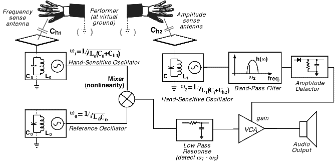
The theremin is a hands-free electronic instrument invented by Leon Theremin in the 20th century. Two antennae act as plates of a capacitor, where your hands act as the second plate to virtual ground. Therefore, the distance between your hand and both antennae increases or reduces the amount of electric charge being pushed around between the antennae and your hands, effectively altering the capacitance of these contrived capacitors. The theremin is engineered to have transfer functions, which act as volume and pitch control, to be proportional these two capacitance values. The user is then able to play this instrument by shifting the position of their hands relative to both antennae to adjust the volume and pitch of the oscillation. See the figures below.


Fig 1 & 2: Radiating antenna on the left, intuition behind workings of theremin on the right. As you can see, the oscillators change frequencies depending on capacitance values produced between the hand and each antenna
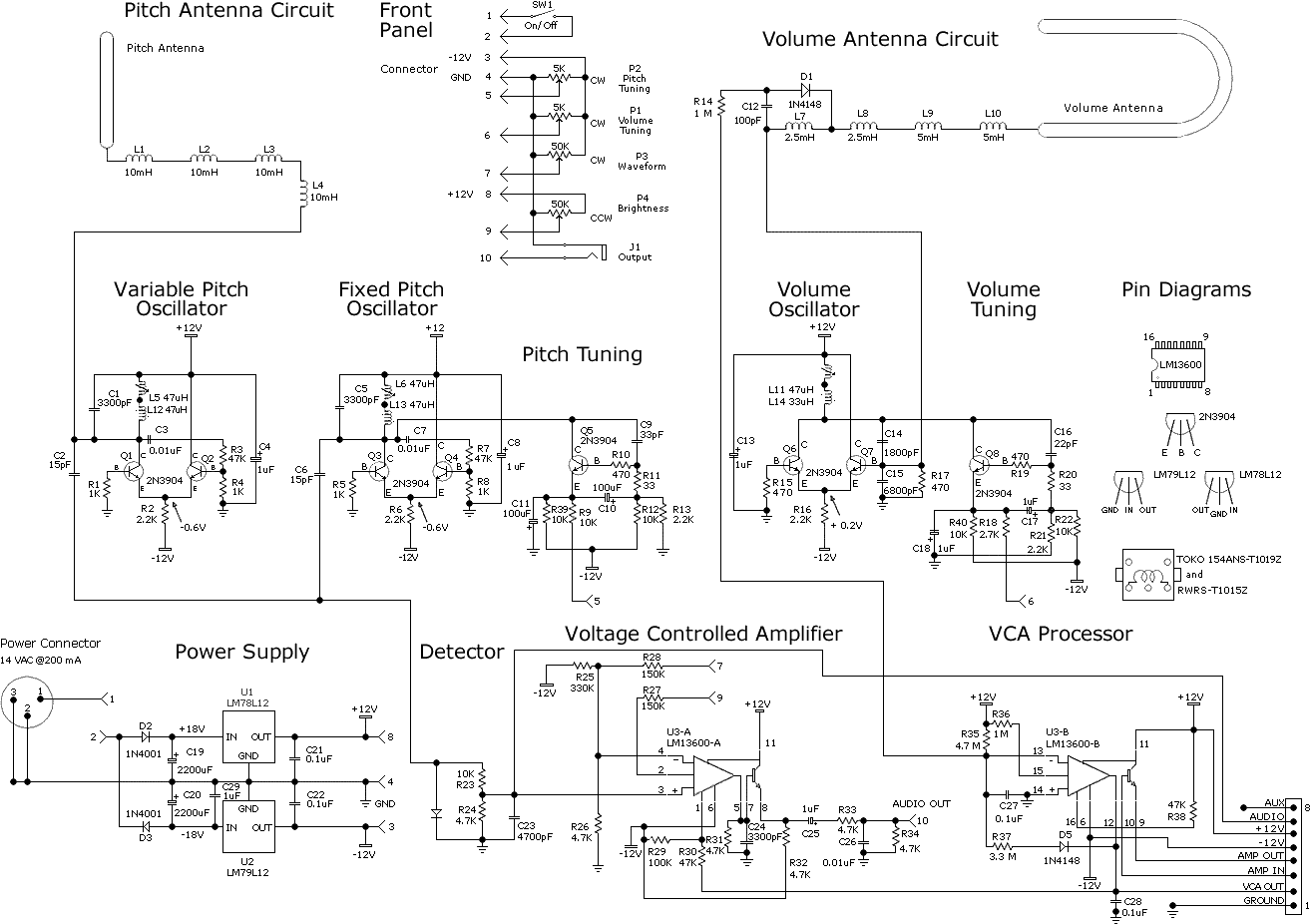
The schematic I am going off of for this project will be the Moog Etherwave (see below). Although there will be adjustments made as needed, most of the construction is pretty straight forward. One of the larger aspects of this project depends less on the construction of the core of the theremin, and more on designing a custom PCB, designing and fabricating my own antennae, tuning the device, and adding modular aspects. One modular aspect I have in mind is rather than playing a pure tone, I use DSP to find the produced frequency and emit a sound-font at the appropriate frequency. This will allow for many different sounds to be installed and played on a theremin, not just your usual sinusoid. Of course the pure analog version will be available as well.

Fig 3: Moog Etherwave circuit this project is based on
Personal Statement:
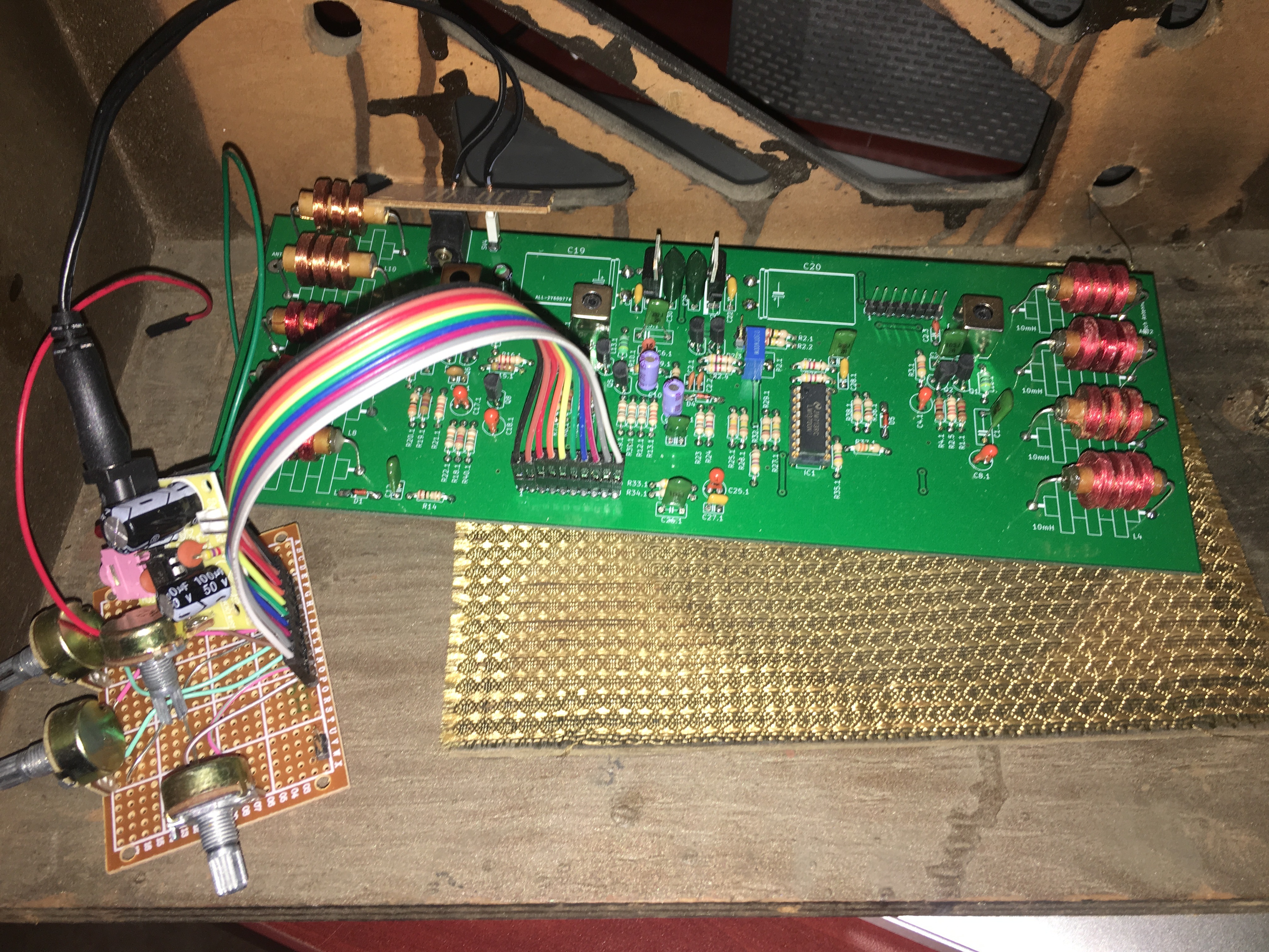
I decided to get into a little competition with my father on who can construct a better theremin. Both being trained as electrical engineers, as well as having a passion for music, this is a fun project to be working on. I would like to say he has more free time on his hands, but it's highly the case that he is simply more disciplined and/or passionate than I am, as he has already designed his theremin PCB, got some copies printed from China, constructed the core of the theremin (see below). I, on the other hand, have begin working on my PCB, but have since stalled due to graduate school and other priorities. The project is currently on hiatus, but I wish to return to it in the near future.

Fig 4: My fathers theremin core. The coils on the left and right will be hooked up to the two antennae, and the pots on the brown breadboard are for tuning purposes
Media Citation(s):
Antenna GIF - http://www.takuichi.net/hobby/edu/em/halfdip/halfdip.html
Simple circuit diagram - https://www.gaudi.ch/OpenTheremin/images/stories/OpenTheremin/Theremin_Principle.gif
In-depth circuit diagram - https://www.cs.nmsu.edu/~rth/EMTheremin.pdf